
SNAPX
A handheld camera I built from an ESP32-CAM, with its own WiFi gallery.
SNAPX is a small digital camera that runs on an ESP32-CAM. It shows a live preview on a 1.8 inch TFT screen, takes a photo when you press a metal shutter button on the side, and saves every shot to the board's internal flash. It also hosts its own WiFi network so you can connect with your phone, open a browser, and download or delete photos without any cable or SD card reader.
Pressing the shutter button. The screen flashes white, freezes on the shot, and shows a saved confirmation before returning to live preview. The onboard LED fires as the flash.
Code
The full Arduino project is on GitHub. It includes the firmware, the web gallery page, and a wiring sketch in the README.
Open GitHub repoCAD
The full enclosure is modeled in Onshape. You can view the parts, measurements, and assembly there, and export it for 3D printing.
Open Onshape documentParts list
These are the exact parts I used. Most of them are cheap and easy to find online. The only thing that is already on the ESP32-CAM board is the flash LED.
AI-Thinker ESP32-CAM board
The classic version with the ESP32 + OV2640 2MP camera sensor.
ESP32-CAM-MB programmer board
Type-C CH340G serial adapter. This lets you flash the camera without unplugging it.
1.8" ST7735S SPI TFT display
128x160, 4-wire SPI. Mine is from DIYmalls. The onboard SD slot is not used.
12mm momentary metal push button
Waterproof, prewired, 1NO. This is the shutter button.
Onboard white LED
Already on the ESP32-CAM board, wired to GPIO4. Used as the flash.
Power supply
A single 18650 cell in a small USB power bank enclosure powers the board over micro USB.
How it is wired
The screen talks to the ESP32-CAM over SPI, the shutter button is just one GPIO pin to ground, and the flash LED is already wired on the board. Power comes from a single 18650 cell through a small USB power bank module.
What the firmware does
The preview loop is simple: the camera sends raw RGB565 pixels straight to the screen in its native format, so there is no JPEG decoding in the loop. A lookup table built at boot handles rotation and scaling. When you press the shutter, the firmware freezes the frame, fires the onboard LED, saves the JPEG to LittleFS, and shows a small saved toast over the photo before returning to preview.
Live preview
RGB565 pixels go straight from the camera to the screen, no JPEG decode in the loop.
Shutter button
A 12mm metal button on GPIO3 with internal pullup, debounced in software.
Flash
The onboard white LED on GPIO4 fires on capture using PWM so it is not too harsh.
Boot screen
A splash screen with a loading bar, then status lines as the sensor, storage, and network come up.
Save toast
Instead of clearing the screen, a small bar draws over the frozen photo to confirm the save.
WiFi gallery
The ESP32 runs an access point and a small web server that lists photos and streams them over WiFi.
Things that fought back
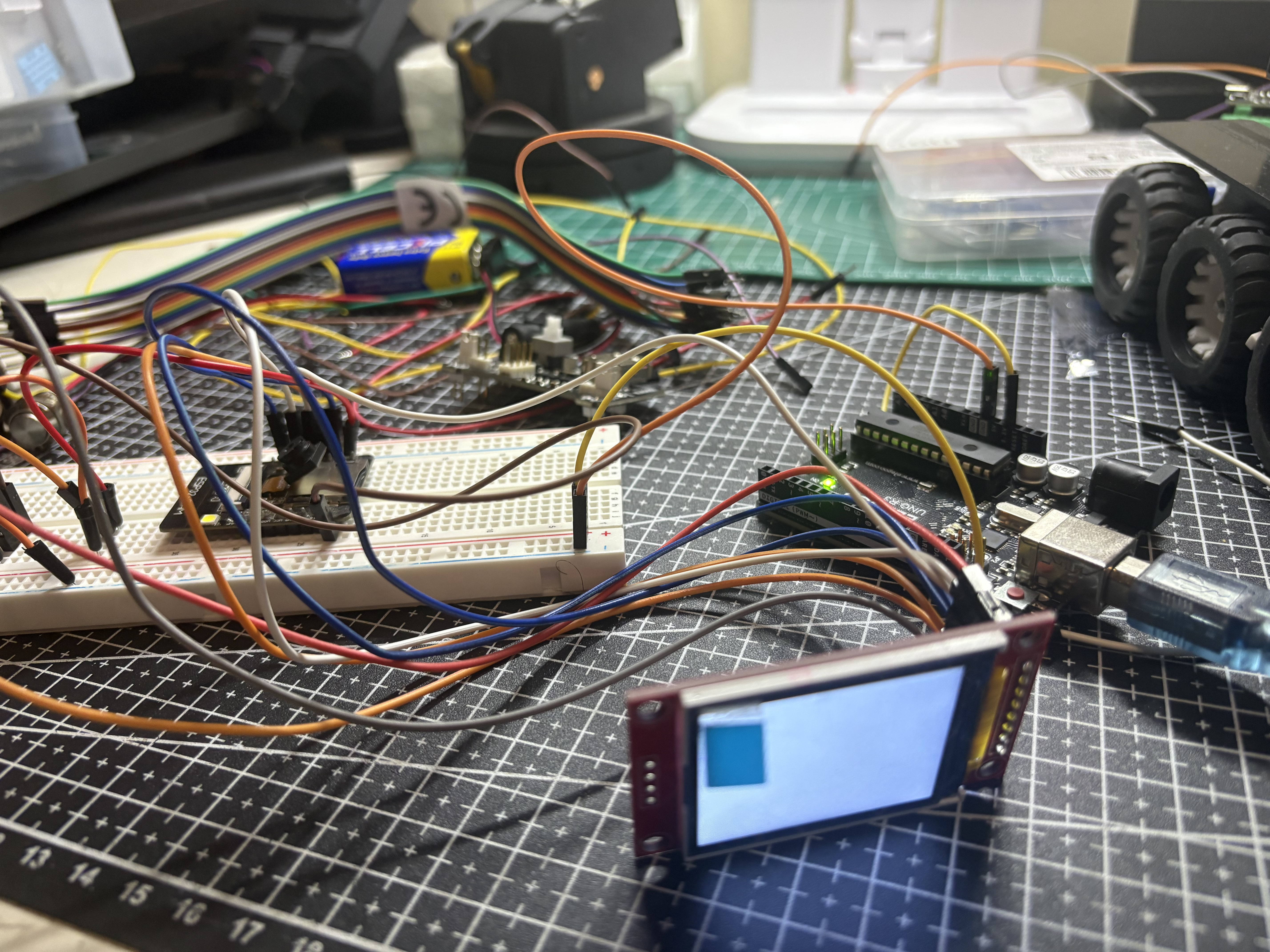
The bench while I was building this. Wires everywhere, a snapped camera ribbon, and a screen that refused to cooperate for days.
Snapped the camera off
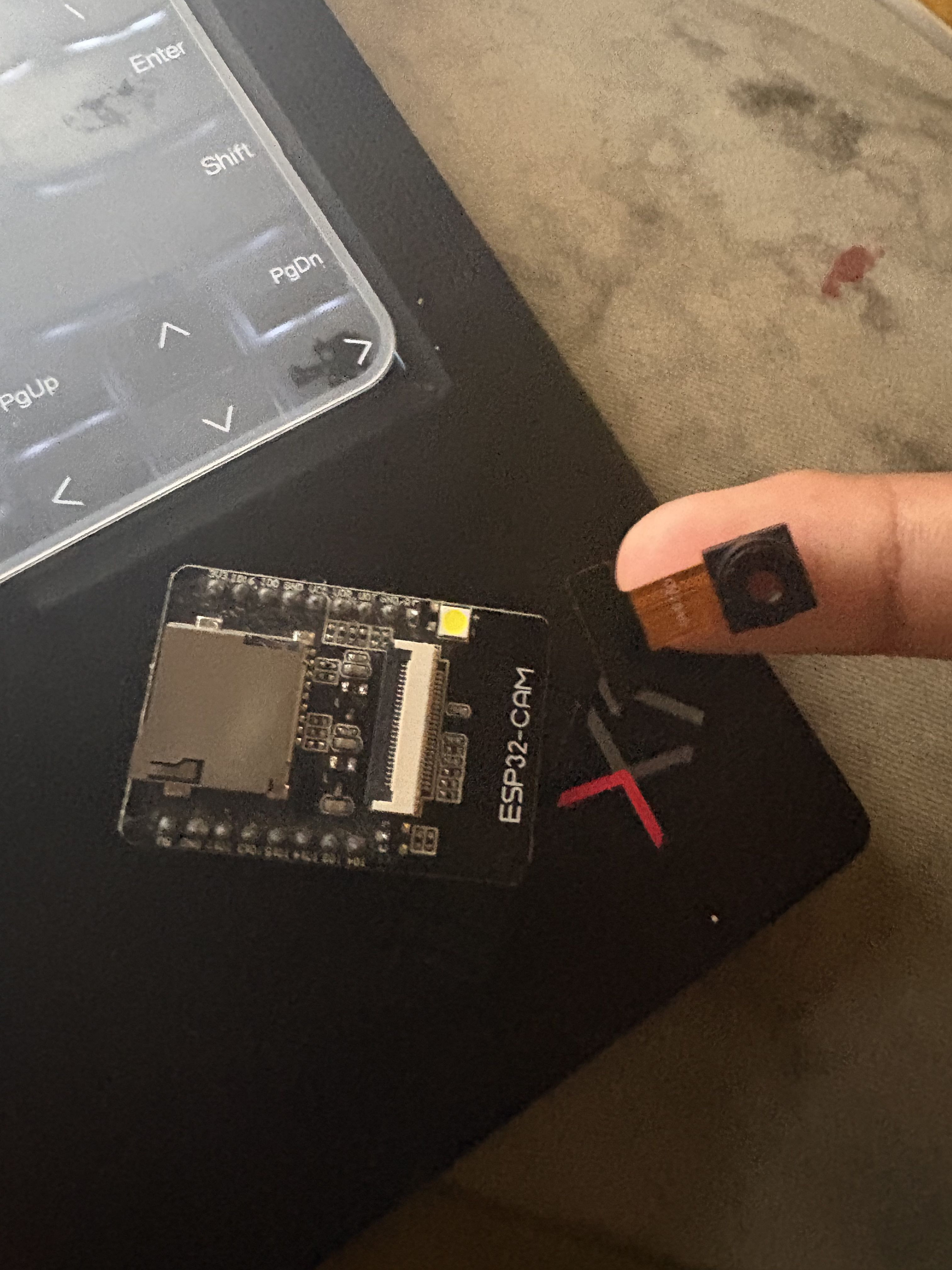
Pulled the ESP32-CAM in and out too many times uploading firmware. The ribbon tore and the sensor stopped being detected. Had to buy a second board with a programmer attachment so the camera could stay seated.
The first photos looked like garbage
Straight out of the box the camera was capturing at low resolution with heavy compression and no sensor tuning. Every shot came out muddy and blurred like this one. Bumping JPEG quality and turning on white balance, gain, exposure and lens correction fixed it.
The screen refused to work
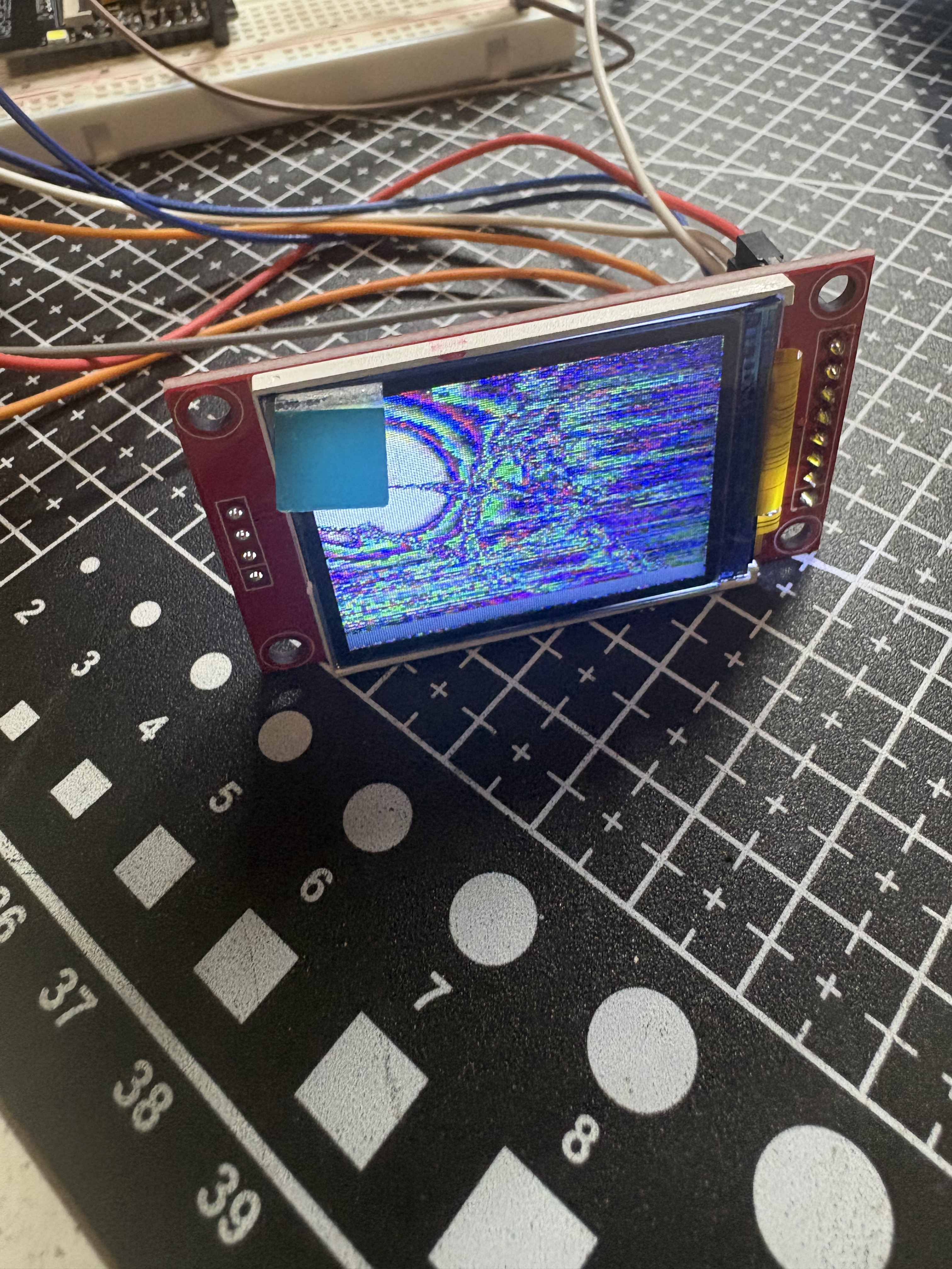
Rewired it maybe seven times. It would flicker, sit white, sometimes flash the right image for a second and go back to rainbow static. Byte order mismatch on the RGB565 stream, wrong write window in the library, and a battery that could not hold voltage under load. All three had to be fixed before it stayed stable.
What went wrong
No auto reset on this board
The classic ESP32-CAM has no USB port and no auto reset circuit, so GPIO0 has to be grounded manually every time you upload. I spent a while thinking my code was not uploading when it was just booting the old firmware.
PSRAM was off
The camera kept failing with a frame buffer malloc error. Turned out the generic ESP32 board profile does not enable PSRAM, so there was no memory to allocate a frame buffer from. Switching to the AI Thinker ESP32-CAM profile fixed it.
I broke the camera ribbon
Because of the upload process I was pulling the camera module in and out constantly, and eventually the ribbon cable gave out. The sensor stopped being detected. Had to buy a new board with a programmer attachment so the camera could stay seated.
Two days on a white screen
The screen would sit white, flicker, sometimes flash the right image for a second then go back to garbage. I rewired it, reflashed it, swapped libraries. The actual problem was the battery. It could not hold voltage once the camera and screen were both drawing. Plugged into USB and the flickering stopped immediately.
The SD card plan did not survive
The screen module has its own SD slot and the original plan was to save photos there. But the camera already eats most of the board's GPIO, and the pins left over for SD chip select and MISO are the same ones the USB programmer uses for serial. I would have had to unplug the SD wiring every time I flashed. So I dropped SD entirely and saved to the ESP32's internal flash with LittleFS, then built the WiFi gallery so I could still get photos off the device.
Rainbow static instead of a picture
Two separate bugs that looked the same. First was a byte order mismatch between the camera's RGB565 output and what the screen expects. Second was the screen library making wrong assumptions about the write window, fixed by setting the address window and writing pixels manually.
Everything ended up sideways
Rotating the display to fix the text orientation also rotated the camera feed 90 degrees. Fixed the feed by rotating in software with precomputed lookup tables, then had to flip the screen rotation temporarily just for drawing text so the status messages were not upside down.
Where the photos land
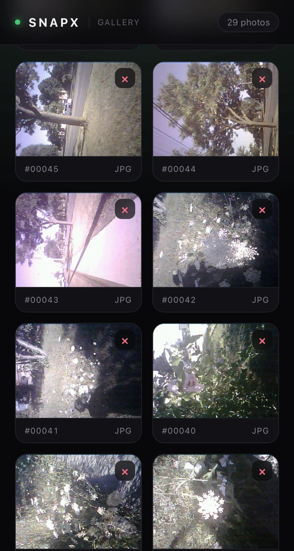
Since there is no SD card, every shot is written to the ESP32's internal flash. The board hosts its own WiFi network and a small web server, so you connect to it from your phone and the gallery loads right in the browser. No app, no cable.
- Grid of every photo on the device with its file number
- Tap any shot to open the full size JPEG
- Delete straight from the browser to free up flash
- Live photo count so you know how much room is left
Shot on SNAPX
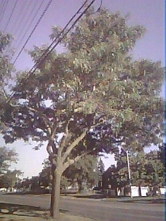
Straight off the camera, no editing. Low res and grainy, but it works.





SNAPX is finished.
Camera is done and working. Code, CAD, and wiring are all here if you want to build one too.